Description:
This document describes how to manually set up a LANCOM VoIP router (in this case a LANCOM 1722 VoIP) for ISDN and SIP providers without using the Setup Wizard.
Requirements:
- A functioning single-line SIP account with a SIP provider of your choice, e.g. Sipgate.
Scenario:
A LANCOM 1722 VoIP router is to enhance an existing ISDN PBX system with Voice over IP.
The LANCOM is connected between the NTBA and the PBX.
The aim of integrating a VoIP provider is for the PBX to place and receive external telephone calls via SIP.
The lifeline should remain functional in case of a failure (e.g. power outage, defect in the LANCOM).
The VoIP Call Manager has not yet been set up, and the device contains the default settings.
Procedure:
Set up the protocols used by the external ISDN S0 connection (TE) and the internal ISDN S0 bus (NT):
1) Open the configuration of the device in LANconfig and go to Interfaces -> WAN -> Interface settings, as shown below. Important here are the two configuration options marked in red.
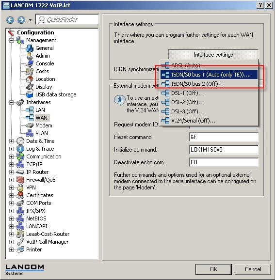
2) Select ISDN/S0 bus 1 to see the following window:
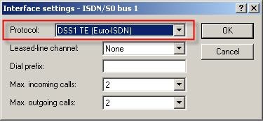
From the drop-down menu, select the protocol used by your ISDN connection.
- DSS1 TE (Euro-ISDN) if you operate a point-to-multipoint connection.
- DSS1 TE point-to-point if you operate a point-to-point connection.
In our example, we have set the protocol DSS1 TE (Euro-ISDN).
3) Select ISDN/S0 bus 2 to see the following window:
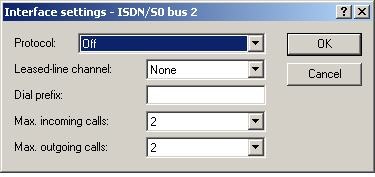
From the drop-down menu, select the protocol used for your ISDN connection.
- DSS1 NT if you operate a point-to-multipoint connection.
- DSS1 NT point-to-point if you operate a point-to-point connection.
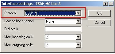
In this example we set the protocol DSS1 NT to match the settings of the ISDN/S0 bus 1:
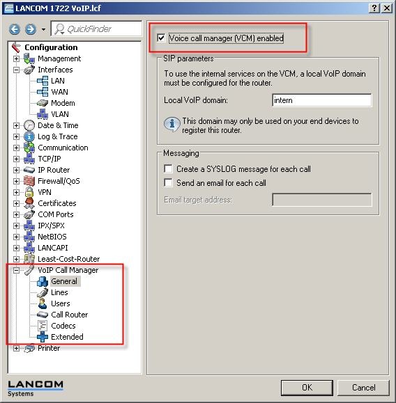
4) In the configuration, change to the VoIP Call Manager.
5) Go to VoIP Call Manager-> General and activate the option Voice Call Manager (VCM) enabled.
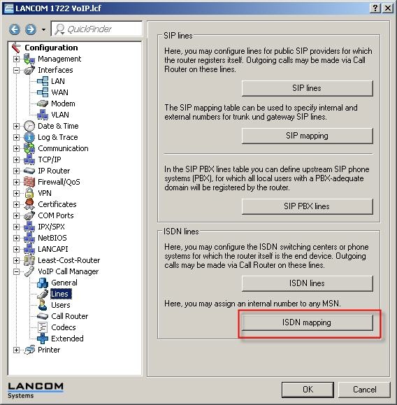
6) The next step is to define the MSNs for your ISDN connection. This is done with the ISDN mapping under VoIP Call Manager-> Lines-> ISDN mapping.
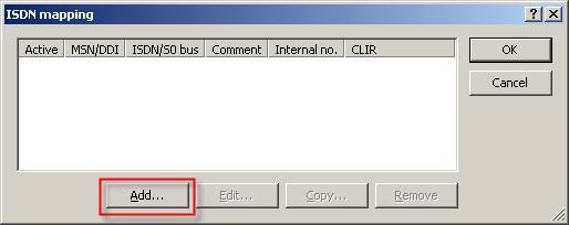
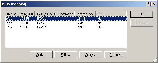
7) Enter the external MSNs of your connection into the ISDN-mapping table with the button Add.
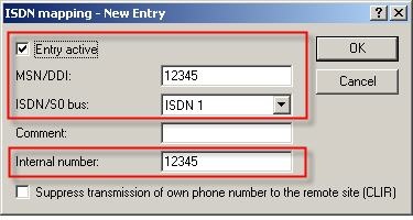
Notes:
- Enter the telephone number of your connection under MSN/DDI. Multiple numbers can be added with a separate entry for each number.
- The switch ISDN/S0 bus determines which interface on the router is to be activated by this telephone number.
- The same number is used for the internal telephone number to save having to reconfigure existing PBX systems or individual telephones. Also, in case the router should fail, the lifeline mode means that the telephones continue to operate because the calls are forwarded directly.
Repeat this procedure for all your phone numbers so that your ISDN mapping looks like the one below (with your numbers, of course):
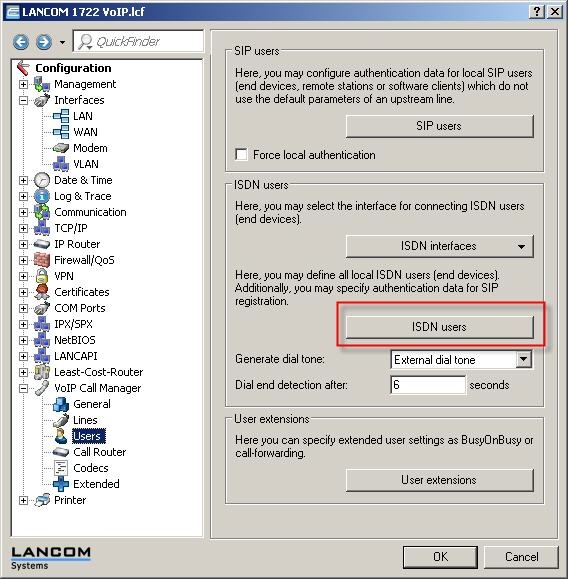
8) Change to VoIP Call Manager -> Users.
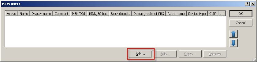
In order for calls to the internal ISDN S0 bus to be forwarded, an ISDN user must be set up for each external MSN from the previous stage. To do this, open the ISDN users table.
9) In the table that opens, use the Add button to add an entry.
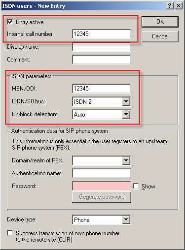
The following dialog opens to make the necessary entries:
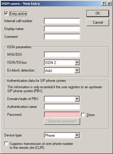
- The internal call number is the user's internal telephone number.
- The MSN/DDI is the actual MSN as stored in the PBX system or in the telephone connected to the LANCOM's internal ISDN S0 bus.
- The setting for ISDN/S0 bus defines the physical port which is connected to the PBX or the telephone.
These are the entries for the first MSN:
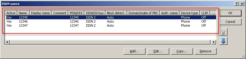
Repeat this procedure for all your phone numbers so that your ISDN users table looks like the one below (with your numbers, of course):
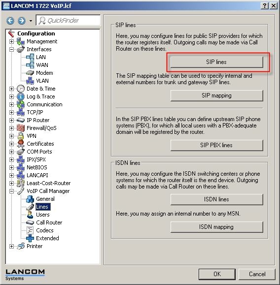
10) In order to make calls via an external VoIP provider, the SIP line now has to be configured.
To do this, return to Voice Call Manager -> Lines and select the button SIP lines.
For new entries press Add... to see the following overview:
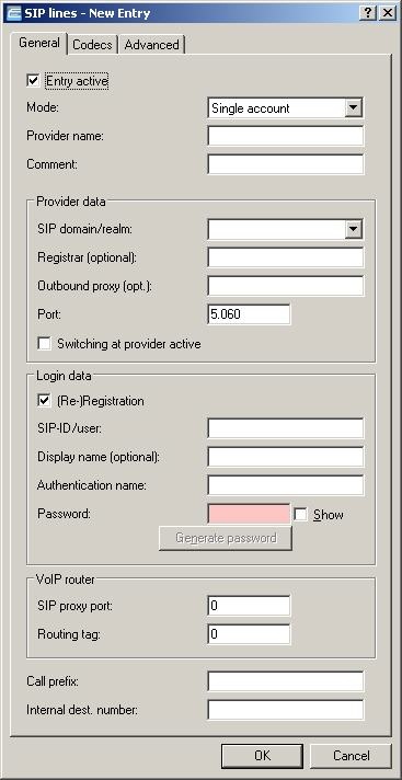
Enter the data given to you by your provider.
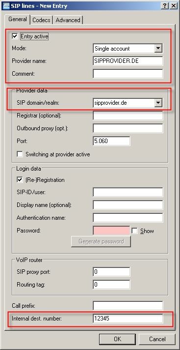
It is important to enter the internal destination number, highlighted above, in addition to the provider data. This identifies which user is to receive the incoming calls to the SIP number. In this case, a call arriving at the PBX is forwarded to the MSN 12345.
Notes:
- In most cases a SIP provider is a single-line account.
- In the next step, select one of the pre-defined SIP providers from the list or enter the login details given to you.
- Enter your user data from the provider in the fields SIP-ID/user and password.
- In some (rare) cases, an authentication name must also be entered.
11) The final stage of the configuration is to set up the Call router.
In LANconfig, change to the VoIP Call Manager-> Call router-> Call routing.
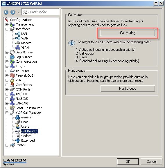
The following table opens up:
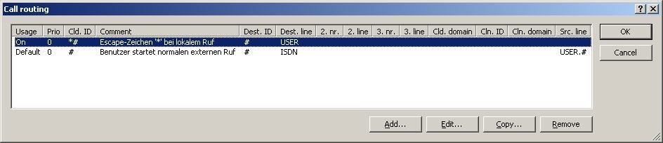
In order to make use of the SIP provider that was just configured, one more entry is required in the Call routing. Use the button Add...
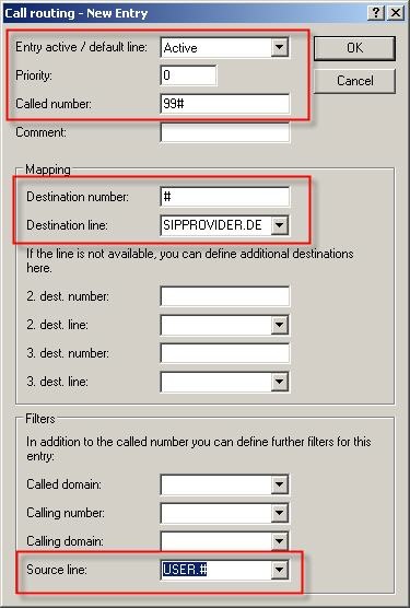
Enter the data into the dialog as illustrated below.
The call-routing table should now appear as follows:
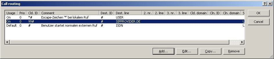
After confirming and writing the configuration back to the device, you can make calls via the SIP provider by entering the prefix 99 (analogous to entering '0' for an outside line).
Notes:
- Each item is described by pop-up help text. Just click on the question mark at the top right of the dialog.
 |
|
