If you use a LANCOM Router with WLAN and want to seperate the wireless networks as well please read this document Image Removed.
Scenario:
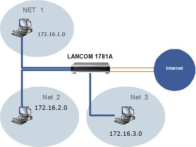
The aim is to restrict access between the
networks
networks Net 1, Net 2and Net 3on the LAN side of the router.
Net 1is a network for employees and should provide access to all other networks and to the Internet.
Net 2is a network for visitors and should provide access to the Internet only.
Net 3is a server network and should not have active access to any other network; however, Net 1should have access to these servers.
Image Removed
Image Added
Net 1:Interface LAN1 (ETH -1), Network ID: 172.16.1.0
Net 2:Interface LAN2 (ETH -2), Network ID: 172.16.2.0
Net 3:Interfaces LAN3 (Eth-3) and LAN4 (Eth-3), Network ID: 172.16.3.0
Procedure:
LANconfig is used to perform the configuration.
A
A LANCOM 1781Ais used for this example scenario.
Interface tags can be allocated to the IP networks. This gives you control over the communication between the networks. Routing tags can be allocated in the routing table.
When combined with the interface tags, these make it possible to control which route may be used by which local network.
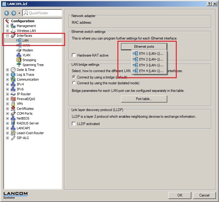
Step 1: Allocating the interfaces to the networks.
1. Open your router's configuration with LANconfig.
Image Removed
Image Added
2. Allocate Ethernet interface 1 to the
logical
logical LAN-1.
Image Removed
Image Added
3. Allocate Ethernet interface 2 to the
logical
logical LAN-2.
Image Removed
Image Added
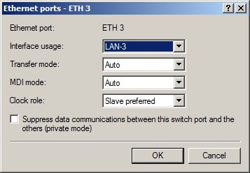
4. Allocate Ethernet interfaces 3 and 4 to the
logical
logical LAN-3.
Image RemovedImage Removed
Image AddedImage Added
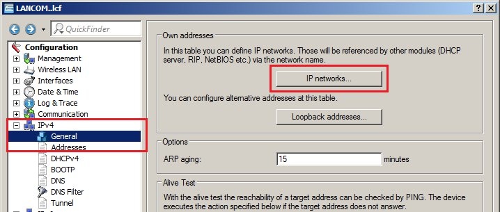
Step 2: Allocating physical interfaces and interface tags to the IP networks.
Hinweis
Note:
Do not delete the entries for the Intranet or the DMZ.
1. Open your router's configuration with LANconfig.
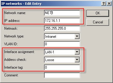
2. Allocate the interface and the interface tag to the IP networks.
IP networks with the interface tag '0' can access all other networks.
IP networks with a tag in the range 1 1-65535 can only access IP networks that use the same interface tag.
Image Removed
Image Added
3.Net 1operates on interface LAN-1and uses interface tag 0, i.e. it can access all other networks.
Image Removed
Image Added
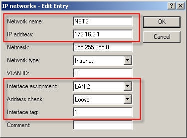
4.Net 2 operates on interface LAN-2and is allocated interface tag 1, i.e. it cannot access any other local network.
Image Removed
Image Added
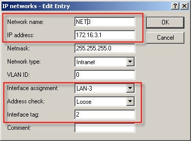
5.Net 3operates on interface LAN-3and is allocated interface tag 2, i.e. it cannot access any other local network.
Image Removed
Image Added
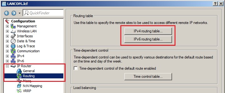
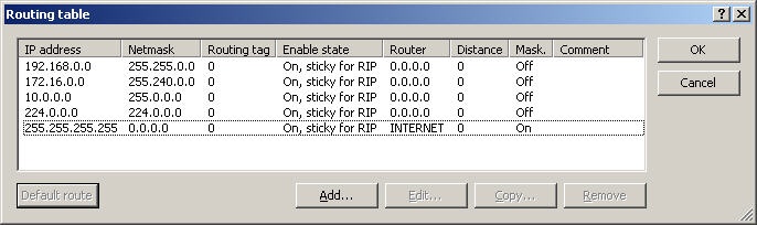
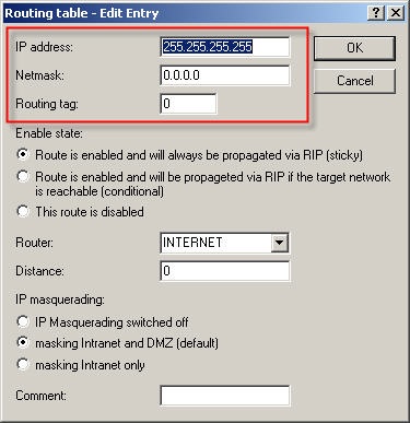
Step 3: Creating the routing entry.
Clients from the networks can us all routes with routing tag 0. If the routing tag is no equal to 0 and not equal to the client’s own interface tag, the route from this network cannot be used.
A default route with routing tag 0 can be used as a connection by all networks.
Image Removed
Image Added
Image Removed
Image Added
Image Removed
Image Added
Optionally:
Info
You can use the command Show bindingsin Telnet or SSH to check that the IP addresses have been allocated to the interfaces.

 .
.