Versionen im Vergleich

Schlüssel

  • Diese Zeile wurde hinzugefügt.
  • Diese Zeile wurde entfernt.
  • Formatierung wurde geändert.
Seiteneigenschaften


Description:

In scenarios with a WLAN point-to-point connection between two sites, the failure of the P2P link could cause production downtime.

In this case it is worthwhile for the P2P link to have a backup over a VPN connection. This requires both locations to have an Internet connection.

This article describes how to set up a P2P link and create a VPN connection as a backup for the P2P link.


Requirements:
  • Both sites already have a configured and functional Internet connection
  • Both sites have separate IP address ranges


Scenario:

1) The P2P link is implemented with separate access points
  • There are two sites: Each site has an access point and a router.
  • The access points support the P2P link
  • The routers use the P2P link between the access points to establish a plain Ethernet connection (IPoE).
  • If the P2P link fails, a VPN connection is established between the two sites.
Image Removed

Image Added


2) The P2P link is established using the WLAN module integrated in the router
  • There are two sites: Each site has a WLAN router.
  • The WLAN routers implement the P2P link
  • The routers use the P2P link between them to establish a plain Ethernet connection (IPoE).
  • If the P2P link fails, a VPN connection is established between the two sites.
Image Removed

Image Added


Procedure:

Scenario 1: The P2P link is implemented with separate access points


Configuration at site A:

1) Configuring router A:

1.1) Set up a VPN connection to router B using the Setup Wizard. This is described in the following article:
DokumentlinksymbolImage Removed
DokumentlinksymbolImage Added


1.2) Set up a plain Ethernet connection (IPoE) as described in the following article:

DokumentlinksymbolImage Removed

DokumentlinksymbolImage Added

    • 1.2.1) Under the
IP parameters
    • , enter a
transfer network
    • used for
communications between routers A and B
    • .

      • IP address: Give router A an IP address from the transfer network.
      • Netmask: Enter the netmask of the transfer network.
      • Default gateway: Enter the IP address of router B in the transfer network (see step 3.2.1).
Important:
The IP address range of the transfer network must not be in use at site A or site B, otherwise problems with routing will occur!
Image Removed
Image Added

  • 1.2.2) Select
Leave the current default route
  • to use the current Internet connection.
Image Removed


Image Added
1.3) Open the configuration of the router in LANconfig and switch to the menu item IP router -> Routing -> IPv4 routing table.
Image Removed

Image Added
  • 1.3.1) Edit the
routing entry of the VPN connection to site B
  • and, under
Router
  • , enter the
IPoE remote site
  • created in
step 1.2
  • .


Important:
  • The item
IP masquerading
  • has to be left at
IP masquerading switched off
  • .
Image Removed


Image Added
1.4) Navigate to the menu Communication -> Call Management -> Backup table.
Image Removed

Image Added
  • 1.4.1) Store the following parameters:

    • Remote site: From the drop-down menu, select the IPoE connection you created in step 1.2.
    • Backup list: Select the VPN remote site (see Step 1.1).
Image Removed

Image Added
Image Removed

Image Added
1.5) Navigate to the menu Communication -> Protocols -> Polling table.
Note:
If you are using an IPoE or DHCPoE connection, ICMP polling must be set up for line monitoring. Otherwise, no backup connection will be established.
Image Removed
Image Added
  • 1.5.1) Create a new entry and enter the following parameters:

    • Remote site: From the drop-down menu, select the IPoE connection created in step 1.2.
    • IP address 1: Enter the IP address of router B in the transfer network (see step 3.2.1).
Image Removed

Image Added
1.6) Write the configuration back to the router. This concludes the configuration of router A.


2) Configuring access point A:

Important:
The access point must be connected to the router’s DSL port.

2.1) Open the configuration for the access point in LANconfig and switch to the menu item IPv4 -> General -> IP networks.
Image Removed

Image Added
  • 2.1.1) Edit the network
INTRANET
  • , assign an
IP address from the transfer network
  • to access point A and enter the relevant
netmask
  • .
Image Removed


Image Added
2.2) Write the configuration back to the access point.

2.3) Set up a WLAN point-to-point link as described in the following article:
DokumentlinksymbolImage Removed
DokumentlinksymbolImage Added

2.4) The configuration of access point A is complete.


Configuration at site B:

3) Configuring router B:

3.1) Set up a VPN connection to router B using the Setup Wizard. This is described in the following article:
DokumentlinksymbolImage Removed
DokumentlinksymbolImage Added

3.2) Set up a plain Ethernet connection (IPoE) as described in the following article:

DokumentlinksymbolImage Removed

DokumentlinksymbolImage Added

    • 3.2.1) Under the
IP parameters
    • , enter a
transfer network
    • used for
communications between routers A and B
    • .

      • IP address: Give router B an IP address from the transfer network.
      • Netmask: Enter the netmask of the transfer network.
      • Default gateway: Enter the IP address of router A in the transfer network (see step 1.2.1).
Important:
The IP address range of the transfer network must not be in use at site A or site B, otherwise problems with routing will occur!
Image Removed
Image Added

  • 3.2.2) Select
Leave the current default route
  • to use the current Internet connection.
Image Removed


Image Added
3.3) Open the configuration of the router in LANconfig and switch to the menu item IP router -> Routing -> IPv4 routing table.
Image Removed

Image Added
  • 3.3.1) Edit the
routing entry of the VPN connection to site A
  • and, under
Router
  • , enter the
IPoE remote site
  • created in
step 3.2
  • .


Important:
  • The item
IP masquerading
  • has to be left at
IP masquerading switched off
  • .
Image Removed


Image Added
3.4) Navigate to the menu Communication -> Call Management -> Backup table.
Image Removed

Image Added
  • 3.4.1) Store the following parameters:

    • Remote site: From the drop-down menu, select the IPoE connection you created in step 3.2.
    • Backup list: Select the VPN remote site (see step 3.1).
Image Removed

Image Added
Image Removed

Image Added
3.5) Navigate to the menu Communication -> Protocols -> Polling table.
Note:
If you are using an IPoE or DHCPoE connection, line monitoring by means of ICMP polling must be set up. Otherwise, no backup connection will be established.
Image Removed
Image Added
  • 3.5.1) Create a new entry and enter the following parameters:

    • Remote site: From the drop-down menu, select the IPoE connection created in step 3.2.
    • IP address 1: Enter the IP address of router A in the transfer network (see step 1.2.1).
Image Removed

Image Added
3.6) Write the configuration back to the router. This concludes the configuration of router B.


4) Configuring access point B:

Important:
The access point must be connected to the router’s DSL port.

4.1) Open the configuration for the access point in LANconfig and switch to the menu item IPv4 -> General -> IP networks.
Image Removed

Image Added
  • 4.1.1) Edit the network
INTRANET
  • , assign an
IP address from the transfer network
  • to
access point B
  • and enter the relevant
netmask
  • . .
Image Removed


Image Added
4.2) Write the configuration back to the access point.

4.3) Set up a WLAN point-to-point link as described in the following article:
DokumentlinksymbolImage Removed
DokumentlinksymbolImage Added

4.4) The configuration of access point B is complete.


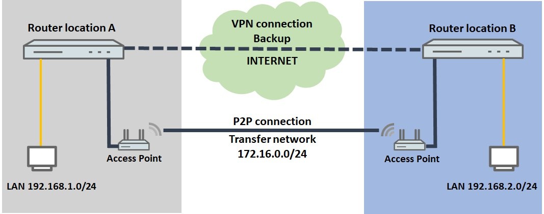
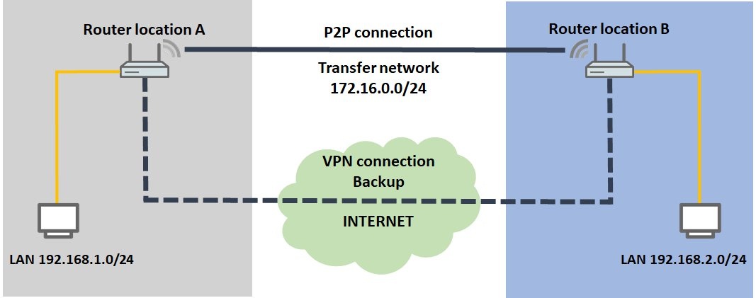
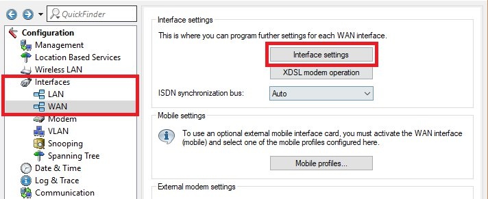
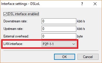
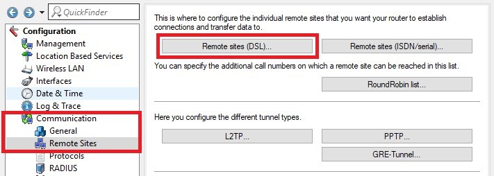
Scenario 2: The P2P link is established using the WLAN module integrated in the router

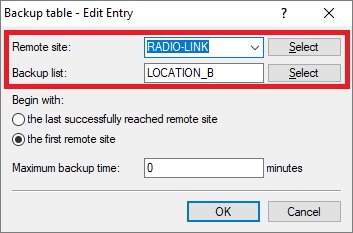
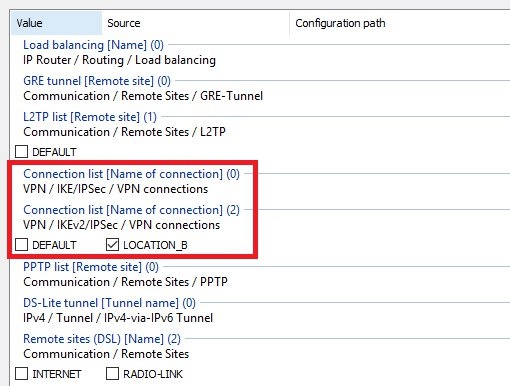
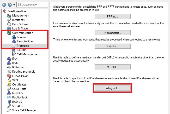
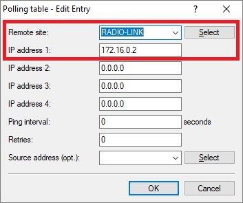
The configuration of the two routers corresponds to that of scenario 1. Some additional adjustments still have to be made.

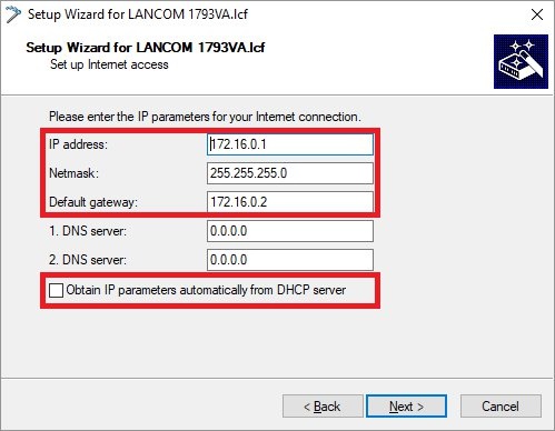
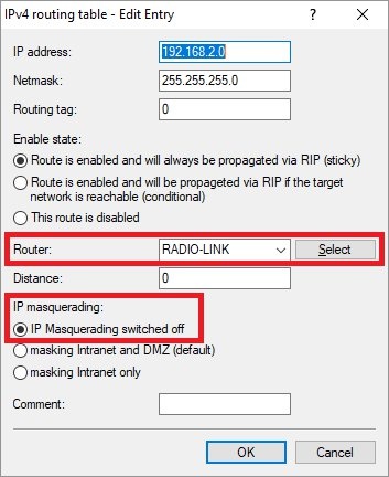
The following steps must be performed on both routers.

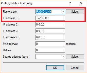
1) Set up a WLAN point-to-point link as described in the following article:

DokumentlinksymbolImage Removed

DokumentlinksymbolImage Added

2) Switch to the menu Interfaces -> WAN -> Interface settings -> DSLoL.

Image Removed


Image Added

  • 2.1) For the
LAN interface
  • , use the drop-down menu to select the
P2P interface
  • used in step 1.
Image Removed


Image Added
3) Switch to the menu Communication -> Remote sites -> Remote sites (DSL).
Image Removed

Image Added
  • 3.1) Edit the
IPoE remote site
  • (see
steps 1.2 and 3.2
  • ) and select the
DSL port
  • for
DSLoL
  • .

    • Router with four LAN ports: DSL port 5
    • Router with two LAN ports: DSL port 2
Image Removed

Image Added