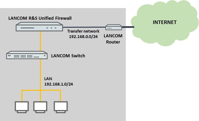
Versionen im Vergleich

Schlüssel

  • Diese Zeile wurde hinzugefügt.
  • Diese Zeile wurde entfernt.
  • Formatierung wurde geändert.
Seiteneigenschaften


Description:
This document describes a way to integrate a LANCOM R&S®Unified Firewall into an existing network and to use that Unified Firewall as the gateway.
Info

To gain access to the upstream LANCOM router from the network of the Unified Firewall no additional routing entries have to be created. The necessary routing entries already are already present because of the Internet connection on the Unified Firewall.


Requirements:
firmware
  • LCOS FX as of version 10.2
  • Functional network with Internet access on the LANCOM router
  • Web browser for configuring the Unified Firewall.

    The following browsers are supported:
    • Google Chrome
    • Chromium
    • Mozilla Firefox
  • Functional network with Internet access on the LANCOM router


Scenario illustrations:
Current situation:

This document assumes a simple network scenario where a LANCOM router operates as a central gateway for the internal network services (e.g. DHCP) and also provides Internet access.

The Internet connection is implemented using the xDSL modem integrated in the LANCOM router or via the WAN interface (for devices without a modem).

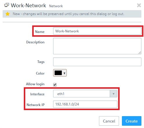
  • The local network (IP address range 192.168.1.0/24) is connected to a LANCOM switch, which the local network components (PC, notebook, server, etc.) are connected to.
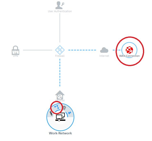
  • This network scenario is to be extended with an additional component, a LANCOM R&S®Unified Firewall.

Image Modified

Target situation:
This way of integrating the Unified Firewall is also referred to as a “series” connection.
  • The Unified Firewall is connected between the LANCOM router and the LANCOM switch.
  • The network address range for the productive network must be changed on the LANCOM router. This will then be used as an intermediate network to the Unified Firewall.
  • On the Unified Firewall, the interface eth0 is used for a WAN connection with an IP address from the intermediate network.
  • The productive network is on the interface eth1 on the Unified Firewall. This then provides all services on the network (such as DHCP) and also acts as the default gateway.

Image Modified

The series connection arrangement described here has the following advantages and disadvantages:
Image Modified

Procedure:
1) Configuring the LANCOM router:
1.1) Open the configuration for the router in LANconfig and switch to the menu item IPv4
->
General
->
IP networks.
Image Modified
1.2) Edit the network INTRANET.
Image Modified
1.3) Enter an IP address from the intermediate network 192.168.0.0/24.
Image Modified
1.4) Switch to the menu IPv4
->
DHCPv4
->
DHCP networks.
Image Modified
1.5) Edit the entry for the network INTRANET and set the option DHCP server enabled to No to disable the DHCP server.
Image Modified
1.6) The LANCOM router has now been configured. Write the configuration back to the router.


2) Configuring the Unified Firewall.
2.1) Setting up the Internet connection to the LANCOM router:
2.1.1) Open the configuration interface of the Unified Firewall in your browser, change to the menu Network
->
Connections
->
Network Connections and click on the chevron icon to enter the advanced view.
Image Modified
2.1.2) Delete the entry for the interface eth0.
Note:
Info

By default the interface

eth0

is set to

DHCP

. However, if possible the IP address should be assigned statically (

Static

), so that

port forwarding

portforwarding can be set up on the upstream router, if necessary.


Image Modified
2.1.3) Click on the “+” icon to create a new connection.
Image Modified
2.1.4) Modify the following parameters:
  • Name: Enter a descriptive name.
  • Interface: From the drop-down menu, select the interface eth0.
  • Type: Check that the value is set to Static.
  • IP Adresses: Enter an IP address from the intermediate network. This has to be entered in CIDR notation (Classless Inter-Domain Routing) (e.g. 192.168.0.254/24).
Image Modified
2.1.5) Change to the WAN tab and modify the following parameters:
  • Set a checkmark next to Default Gateway.
  • Default Gateway: Enter the IP address of the LANCOM router in the intermediate network (see step 1.3).
Image Modified

2.2) Setting up the local network on the Unified Firewall:
2.2.1) Modify the entry for the interface eth1.
Image Modified
2.2.2) Modify the following parameters:
  • Name: Enter a descriptive name.
  • IP Adresses: Make sure that an IP address from the productive network has been entered. This must be in CIDR notation (e.g. 192.168.1.254/24).
Note:
Info

The default the physical interface eth1 is set with the IP address 192.168.1.254.

Image Modified


2.3) Activating the DHCP server on the Unified Firewall:
2.3.1) Navigate to the menu Network
->
DHCP Settings.
Image Modified
2.3.2) Modify the following parameters:
  • Activate the DHCP server by clicking the switch.
  • Set a checkmark for Prevent IP Conflicts to allow the Unified Firewall to check for the availability of an address with a ping.
Image Modified
2.3.3) Modify the entry for the interface eth1.
Image Modified
2.3.4) Activate DHCP address assignment by clicking the switch and, from the drop-down menu Network, select the IP network associated with interface eth1. The remaining parameters are entered automatically.
Note:
Info

If required, you can adjust the parameters such as the DHCP address range or the DNS servers.

Image Modified

2.4) Creating the desktop objects:
2.4.1) Click the button to Create an Internet object.
Image Modified
2.4.2) Modify the following parameters:
  • Object Name: Enter a descriptive name.
  • Connections: From the drop-down menu, select the WAN Object created in steps 2.1.4 - 2.1.5 and click on the “+” icon to enter the object.
Image Modified
2.4.3) Click the button to create a network.
Image Modified
2.4.4) Modify the following parameters:
  • Name: Enter a descriptive name.
  • Interface: From the drop-down menu, select the interface eth1.
  • Network IP: Click in the input field to automatically enter the network assigned to interface eth1.

Image Modified


2.5) Allow communication from the local network to the Internet:
2.5.1) On the desktop, click the network object and select the Connection Tool. Link the network object to the Internet object.

Image Modified
2.5.2) For the outgoing communications, add the necessary protocols by means of the “+” icon.
Image Modified

2.6) Saving and activating the configuration steps:
2.6.1) Click on the Activate button to accept and enable the changes.
Image Modified

2.7) Further steps Configuring the UTM features:
The configuration of the UTM functions is described in the following articles:
DokumentlinksymbolImage Removed
Image Removed
DokumentlinksymbolImage Removed
URL/Content FilterDokumentlinksymbolImage Removed