Description:
This document describes how to manually set up a VPN site-to-site connection between two LANCOM routers, i.e. without using the Setup Wizard. The VPN connection is to be established in the main mode.
To use main mode connections, both ends of the connection require a public IP address for authentication. A DynDNS entry is considered to be fixed public IP address.
Requirements:
- Functional IPv6 Internet connection at both ends.
Scenario:
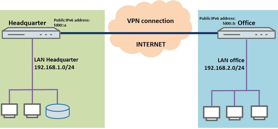
- A company wishes to interconnect the local networks at their headquarters and at a branch office by means of a site-to-site VPN connection.
- Both sites have a LANCOM router as their gateway and an IPv6 Internet connection with a fixed IP address. The IPv6 address of the Headquarters is fd00::a, and the branch office is fd00::b.
- The VPN connection is established from the branch office to the headquarters.
- The local network at the headquarters has the IP address range 192.168.1.0/24, and the branch office uses the local IP address range 192.168.2.0/24.
Procedure:
1) Manual configuration of the LANCOM router at the headquarters:
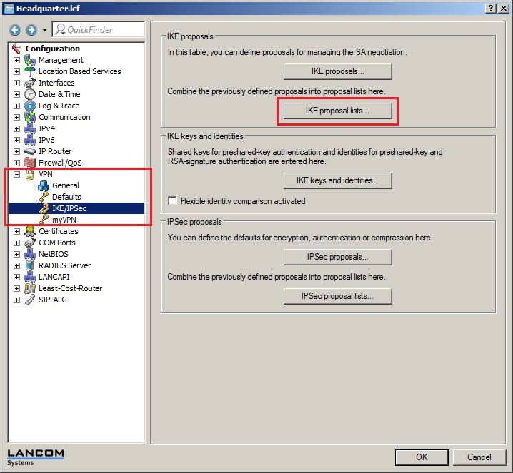
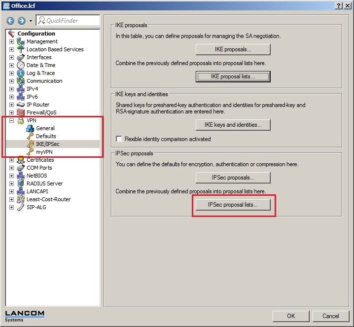
1.1) Open the configuration for the LANCOM router at the branch office and switch to the menu item VPN -> IKE/IPSec.
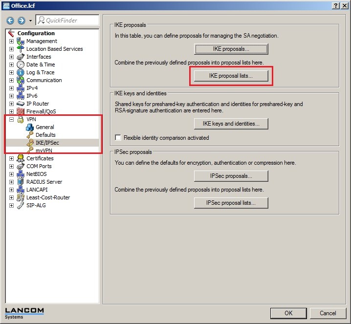
1.2) Click the IKE proposal lists button.
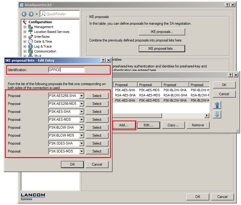
1.3) Create a new IKE proposal list. Name it OFFICE and fill out the proposal list with the IKE proposals that should be used. You can enter one or several IKE proposals.
Note:
From the list of proposals, the first IKE proposal that matches at both ends of the VPN connection is used to establish the IKE Phase 1.
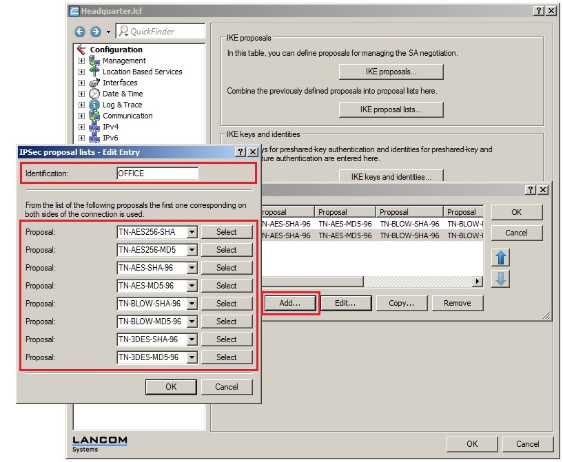
1.4) Click the IPSec proposal lists button.
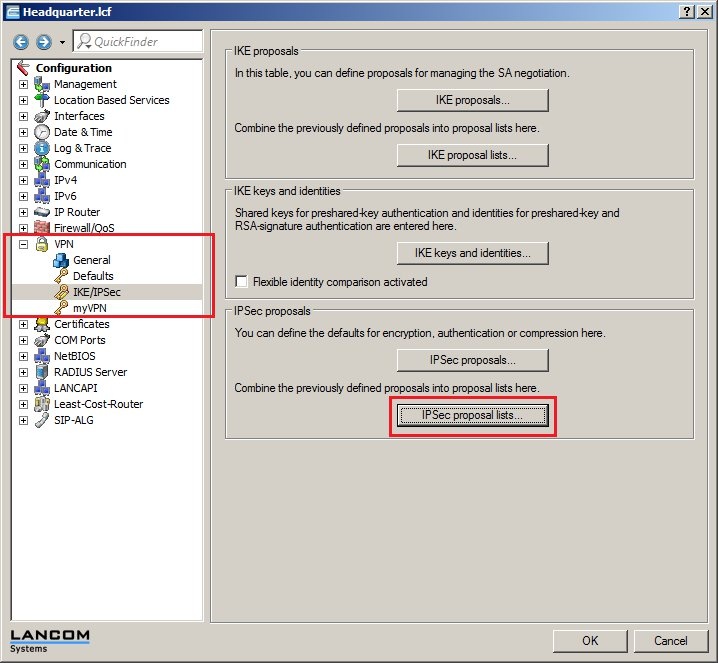
1.5) Create a new IPSec proposal list. Name it OFFICE and fill out the proposal list with the IPSec proposals that should be used. You can enter one or several IPSec proposals.
Note:
From the list of proposals, the first IPSec proposal that matches at both ends of the VPN connection is used to establish the IPSec Phase 2.
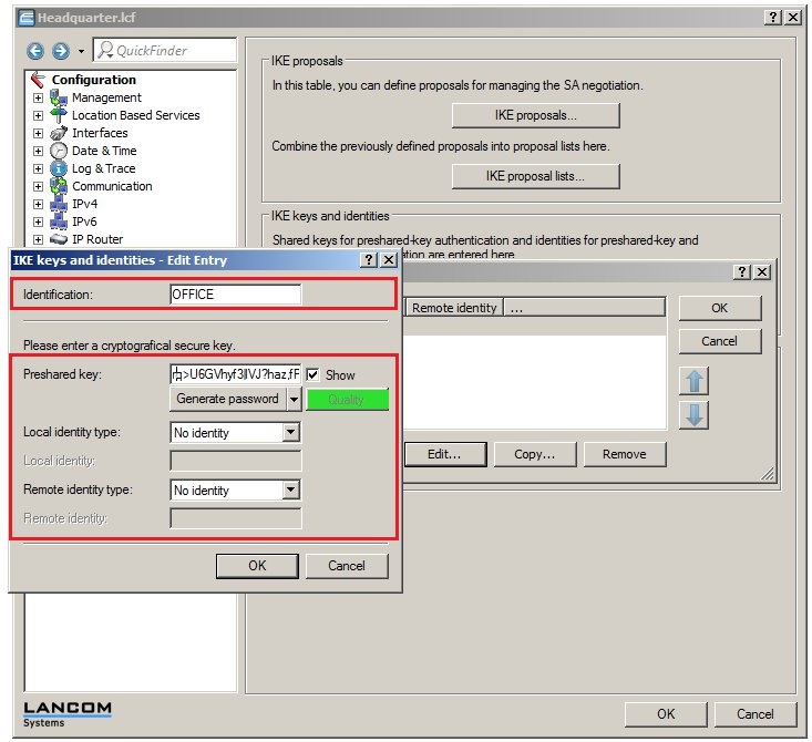
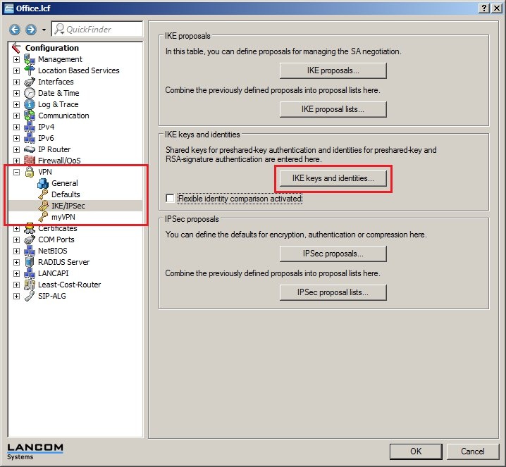
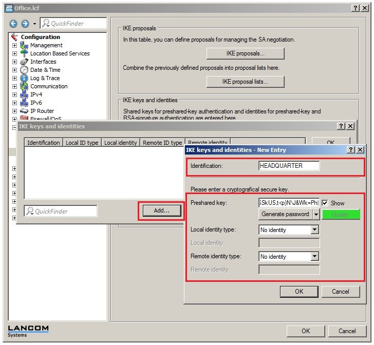
1.6) Click the IKE keys and identities button.

1.7) Create a new entry. Enter the identification OFFICE and, in the preshared key box, enter a sufficiently secure password. At both ends of the connection, the options Local & Remote identity type need to be set to the values No identity.
Note:
You can use the button
Generate password to select a password strength and then automatically generate a password corresponding to this strength. We recommend that you use the setting
Maximum here.
If you select
User defined , you can influence the automatically generated password in the
Settings pane, although for security reasons you should
not change the default settings .
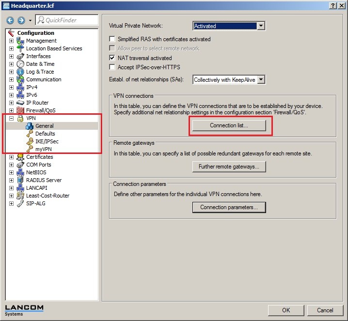
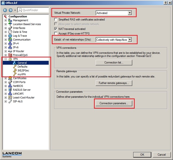
1.8) Switch to the menu VPN-> General.
- Enable the VPN feature of the LANCOM router.
- Set the option Establ. of net relationships (SAs) to the value Collectively with KeepAlive.
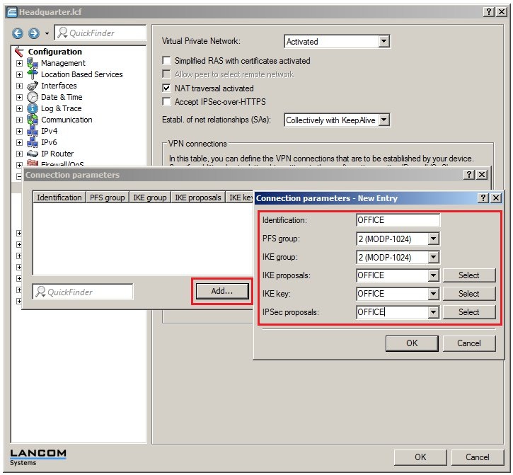
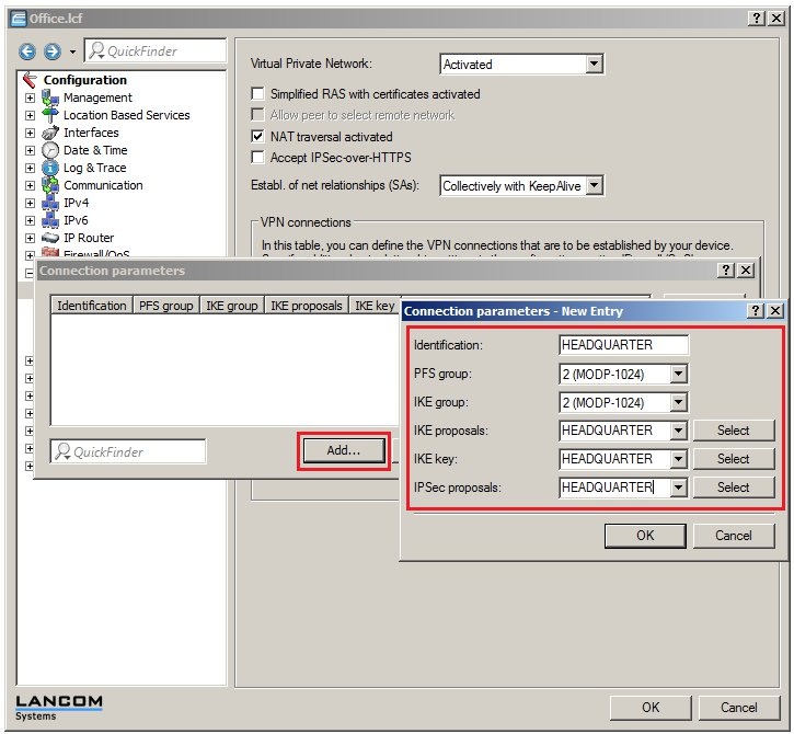
1.9) Then click the Connection parameters button.

1.10) Add a new entry. Enter the identification OFFICE and select the entries of the same name for the IKE proposals, IKE key and IPSec proposals.
The PFS and IKE groups in this example are each set to the default group 2 (MODP-1024). You can change these value to suit your needs. However, make sure that both ends of the VPN connection are set with the same PFS and IKE groups.
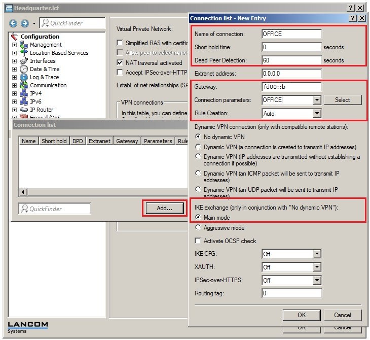
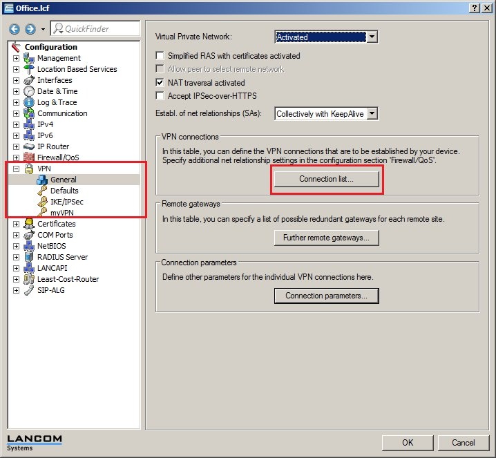
1.11) Click the Connection list button.
1.12) Add a new entry. Set the name to OFFICE and select the values for the fields as follows:
- The LANCOM router at the headquarters will be accepting the VPN connection, so the value for the short-hold time must be set to 0 seconds here.
- The Dead Peer Detection is used for monitoring the VPN connection. Enter the value of 60 seconds here. For more information about the Dead Peer Detection, see the following KnowledgeBase article
 . .
- In the field for the remote Gateway, you need to enter the IPv6 address of the LANCOM router at the branch office. In this example it is fd00::b.
- Set the Connection parameters to OFFICE.
- The Rule creation is carried out automatically in this example.
Using this method, the LANCOM router sets up the network relationships between the IP networks that are set to network type INTRANET under IPv4 -> General -> IP networks and the IP networks that are to be found under IP router -> Routing -> IPv4 routing table behind the corresponding VPN remote station.
- The IKE exchange mode needs to be set to the option Main mode.
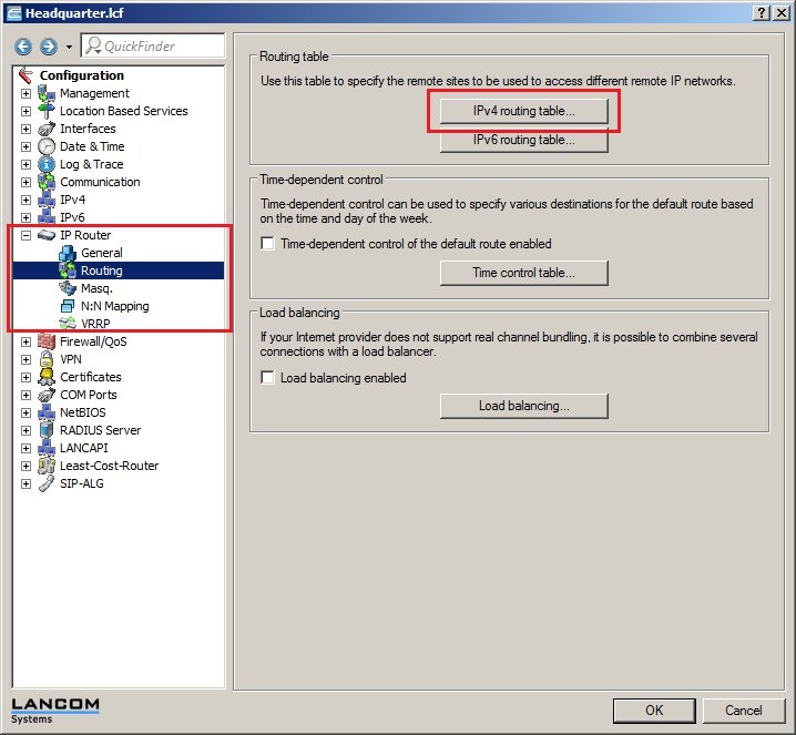
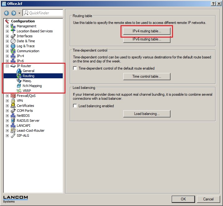
1.13) Navigate to the menu IP router -> Routing -> IPv4 routing table.
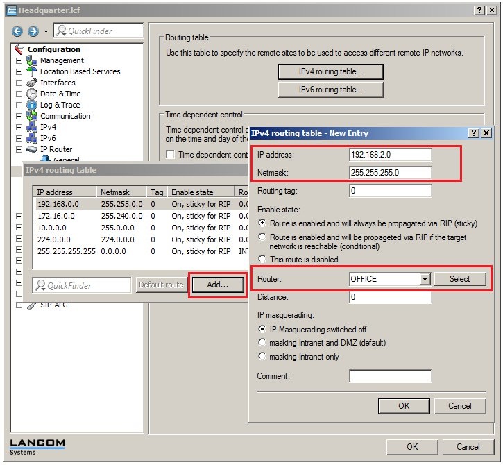
1.14) Add a new routing entry.
- As the IP address, enter the address of the local network at the branch office. In this example it is 192.168.2.0.
- The netmask needs to be set to the value 255.255.255.0 as the local network at the branch office is a class C network.
- For the Router field, select the identification of the VPN remote station (in this case: OFFICE).
1.15) Write the configuration back to the LANCOM router.
2) Manual configuration of the LANCOM router at the branch office:
2.1) Open the configuration for the LANCOM router at the branch office and switch to the menu item VPN -> IKE/IPSec.
2.2) Click the IKE proposal lists button.
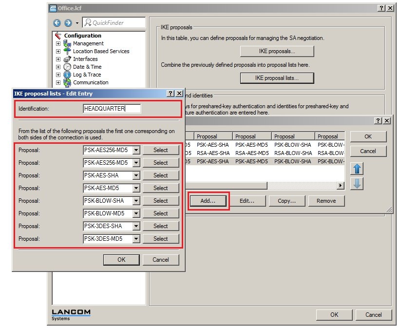
2.3) Create a new IKE proposal list. Name it HEADQUARTERS and fill out the proposal list with the IKE proposals that should be used. You can enter one or several IKE proposals.
Note:
Make sure that the same IKE proposals are entered into this list as those used by the LANCOM router at the headquarters (see step 1.3).
2.4) Click the IPSec proposal lists button.
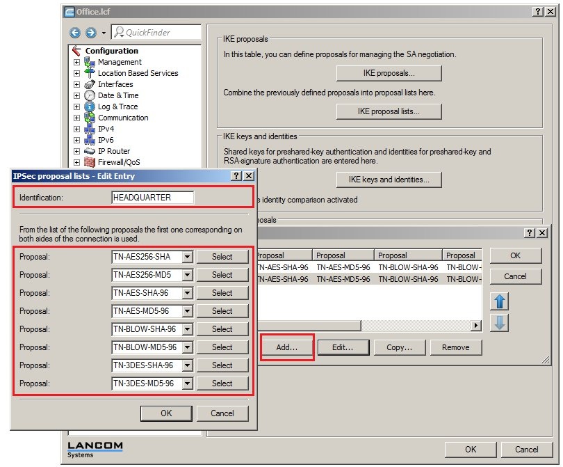
2.5) Create a new IPSec proposal list. Name it HEADQUARTERS and fill out the proposal list with the IPSec proposals that should be used. You can enter one or several IPSec proposals.
Note:
Make sure that the same IPSec proposals are entered into this list as those used by the LANCOM router at the headquarters (see step 1.5).
2.6) Click the IKE keys and identities button.
2.7) Create a new entry. Set the identification to HEADQUARTERS and enter the same password into the Preshared key field as that used by the LANCOM router at the headquarters (see step 1.7).
At both ends of the connection, the options Local & Remote identity type need to be set to the values No identity.
2.8) Switch to the menu VPN-> General.
- Enable the VPN feature of the LANCOM router.
- Set the option Establ. of net relationships (SAs) to the value Collectively with KeepAlive.
2.9) Then click the Connection parameters button.
2.10) Add a new entry. Enter the identification HEADQUARTERS and select the entries of the same name for the IKE proposals, IKE key and IPSec proposals.
The PFS and IKE groups in this example are each set to the default group 2 (MODP-1024). You can change these value to suit your needs. However, make sure that both ends of the VPN connection are set with the same PFS and IKE groups.
2.11) Click the Connection list button.
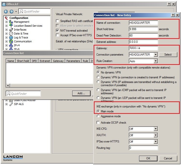
2.12) Add a new entry. Set the name to HEADQUARTERS and select the values for the fields as follows:
- The LANCOM router at the branch office will be actively establishing the VPN connection to the headquarters, so the value for the short-hold time must be set to 9,999 seconds here.
- The Dead Peer Detection is used for monitoring the VPN connection. Enter the value of 60 seconds here.
- In the field for the remote Gateway, you need to enter the IPv6 address of the LANCOM router at the HEADQUARTERS. In this example it is fd00::a.
- Set the Connection parameters to HEADQUARTERS.
- The Rule creation is carried out automatically in this example.
Using this method, the LANCOM router sets up the network relationships between the IP networks that are set to network type INTRANET under IPv4 -> General -> IP networks and the IP networks that are to be found under IP router -> Routing -> IPv4 routing table behind the corresponding VPN remote station.
- The IKE exchange mode needs to be set to the option Main mode.
2.13) Navigate to the menu IP router -> Routing -> IPv4 routing table.
2.14) Add a new routing entry.
- As the IP address, enter the address of the local network at the headquarters. In this example it is 192.168.1.0.
- The netmask needs to be set to the value 255.255.255.0 as the local network at the headquarters is a class C network.
- For the Router field, select the identification of the VPN remote station (in this case: HEADQUARTERS).
2.15) Write the configuration back to the LANCOM router.
After the configuration has been written back to the LANCOM router at the branch office, the VPN connection can be established between the two LANCOM routers. You can check this for example by loading the two LANCOM routers into the LANmonitor.
Note:
If problems occur during connection establishment, or if the established VPN connection does not work properly, a VPN Status Trace can help with the diagno sis. Information is available in the following KnowledgeBase article
 . .
|
|
